Computer Networking: A Top-Down Approach
Table of Contents
- Overall Thoughts
- High-Level Summary
- Notes
- Chapter 1 — Computer Networks and the Internet
- 1.1 — What is the Internet?
- 1.2 — The Network Edge
- 1.3 — The Network Core
- 1.4 — Delay, Loss, and Throughput in Packet-Switched Networks
- 1.4.1 Overview of Delay in Packet-Switched Networks
- 1.4.2 Queuing Delay and Packet Loss
- 1.4.3 End-to-End Delay
- 1.4.4 Throughput in Computer Networks
- 1.5 — Protocol Layers and Their Service Models
- 1.6 — Networks Under Attack
- 1.7 — History of Computer Networking and the Internet
- Chapter 2 — Application Layer
- 2.1 — Principles of Network Applications
- 2.1.1 Network Application Architectures
- 2.1.2 Processes Communicating
- 2.1.3 Transport Services Available to Applications
- 2.1.4 Transport Services Provided by the Internet
- 2.1.5 Application-Layer Protocols
- 2.1.6 Network Applications Covered in This Book
- 2.2 — The Web and HyperText Transfer Protocol (HTTP)
- 2.2.1 Overview of HTTP
- 2.2.2 Non-Persistent and Persistent Connections
- 2.2.3 HTTP Message Format
- 2.2.4 User-Server Interaction: Cookies
- 2.2.5 Web Caching
- 2.3 — Electronic Mail in the Internet
- 2.4 — DNS — The Internet's Directory Service
- 2.5 — Peer-to-Peer File Distribution
- 2.6 — Video Streaming and Content Delivery Networks
- 2.6.1 Internet Video
- 2.6.2 HTTP Streaming and Dynamic Adaptive Streaming over HTTP (DASH)
- 2.6.3 Content Distribution Networks (CDNs)
- 2.6.4 Case Studies: Netflix, YouTube, and KanKan
- 2.7 — Socket Programming
- Chapter 3 — Transport Layer
- 3.1 — Introduction and Transport-Layer Services
- 3.1.1 Relationship Between Transport and Network Layers
- 3.1.2 Overview of the Transport Layer in the Internet
- 3.2 — Multiplexing and Demultiplexing
- 3.3 — Connectionless Transport: UDP
- 3.4 — Principles of Reliable Data Transfer
- 3.4.1 Building a Reliable Data Transfer Protocol
- 3.4.2 Pipelined Reliable Data Transfer Protocols
- 3.4.3 Go-Back-N
- 3.4.4 Selective Repeat
- 3.5 — Connection-Oriented Transport: TCP
- 3.5.1 The TCP Connection
- 3.5.2 TCP Segment Structure
- 3.5.3 Round-Trip Time Estimation and Timeout
- 3.5.4 Reliable Data Transfer
- 3.5.5 Flow Control
- 3.5.6 TCP Connection Management
- 3.6 — Principles of Congestion Control
- 3.7 — TCP Congestion Control
- Chapter 9 — Multimedia Networking
- 9.1 — Multimedia Networking Applications
- 9.2 — Streaming Stored Video
- 9.3 — Voice-over-IP (internet telephony, VoIP)
- 9.3.1 Limitations of the Best-Effort IP Service
- 9.3.2 Removing Jitter at the Receiver for Audio
- 9.3.3 Recovering from Packet Loss
- 9.3.4 Case Study: VoIP with Skype
- 9.4 — Protocols for Real-Time Conversational Applications
- 9.5 — Network Support for Multimedia
- Sources
Overall Thoughts
I had a lot of fun reading this book. Learning about dozens of protocols in full detail paints a vivid picture of how the Internet actually works. Tangents about real-world applications, system design and Internet history provide nice motivation, and help you engage with the material by making you wonder. The end-of-chapter interviews with networks legends were always fun to read. There are countless references to a broad range of relevant and interesting external materials — from must-know software tools to foundational research papers.
It is very readable for someone with an academic computer science background, and probably readable by someone with some general computer science familiarity who is willing to do their fair share of Googling.
A lot of information is covered at a great pace and depth. The first five chapters teach core networks concepts; chapters 6 to 9 are advanced topics — a fun way to test and expand upon your core networks knowledge.
I should note that before reading this book in full, I had already taken a computer networks class in college which heavily referenced this book. Thus, I was familiar with most of the concepts ahead of time. Additionally, I did not take notes for chapters 4, 5, 6, 7 or 8. If enough people want me to badly enough, I can be convinced, but otherwise this is very low on my to-do list.
High-Level Summary
Computer networks are formed via interconnected protocol-executing machines. The protocols are established by large communities and are documented in RFCs. There are several important characteristics of protocols:
- Packet structure and length
- Initiation and termination
- Error detection and correction
- Reliability
- Security
Combinations of protocols can be used to aggregate properties — the OSI model defines general protocol paradigms. Protocols tend to be modelled with state machines.
The Internet consists of end-users and routers, that identify and find each other via IP addresses, DNS, and routing tables.
Many Internet resources need to be managed:
- IP address space
- DNS and routing table entries
- Throughput
- Multiplexing
- Congestion control
General architectures have been created for high-throughput services, such as content delivery networks and data centers.
Several Internet utility programs exist, such as traceroute, ping, and nslookup.
The economics of the Internet is a function of end-users paying competing Internet Service Providers (ISPs), and ISPs paying competing Autonomous Systems (ASs).
Notes
Chapter 1 — Computer Networks and the Internet
1.1 — What is the Internet?
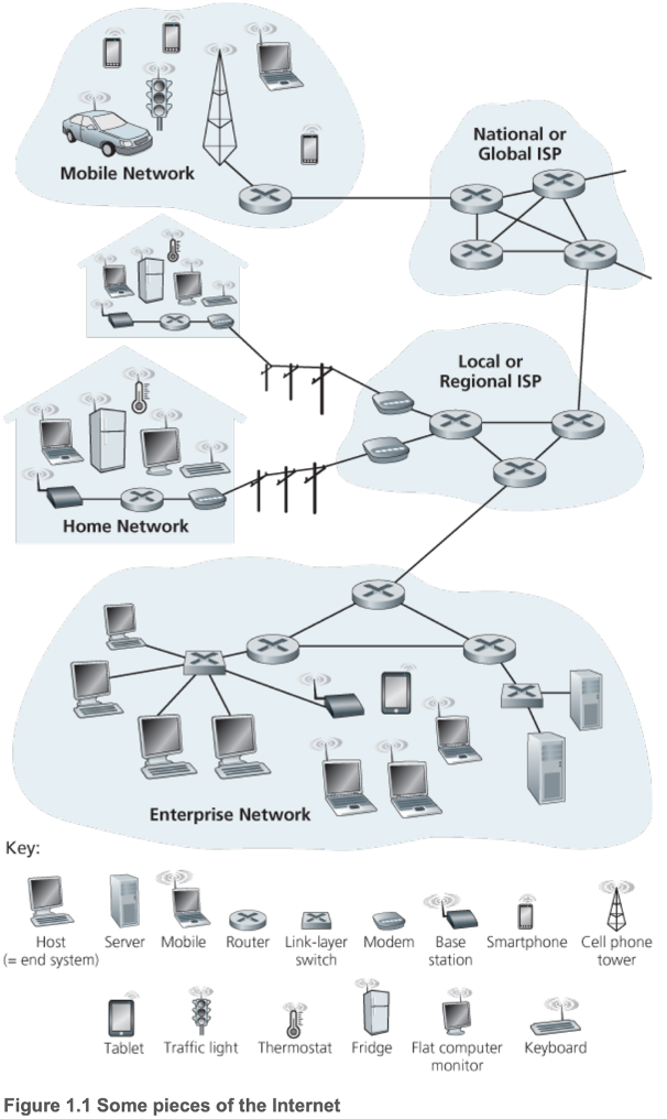
- 1.1.1 A Nuts-And-Bolts Description
- End systems/hosts connected by a network of communication links and packet switches
- Hardware and software components
- End systems/hosts access the Internet through lower-tier Internet Service Providers (ISPs), which are interconnected through national and international upper-tier ISPs
- Protocols are run to control the sending and receiving of information
- TCP/IP
- Internet standards developed by the Internet Engineering Task Force (IETF), whose standard documents are requests for comments (RFCs)
- 1.1.2 A Services Description
- Infrastructure that provides services to distributed applications
- Distributed since they run on multiple end systems
- End systems and the Internet provide a socket interface for communication
- 1.1.3 What Is a Protocol?
- Defines the format and order of messages exchanged between two or more communicating entities, as well as the actions taken on the transmission and/or receipt of a message or other event
1.2 — The Network Edge
- Internet of Things (IoT) — concept of loads of things (besides traditional computers) being connected to the Internet (watches, glasses, thermostats)
- Hosts
- Host application programs
- Clients or servers
- 1.2.1 Access Networks
- Digital Subscriber Line (DSL)
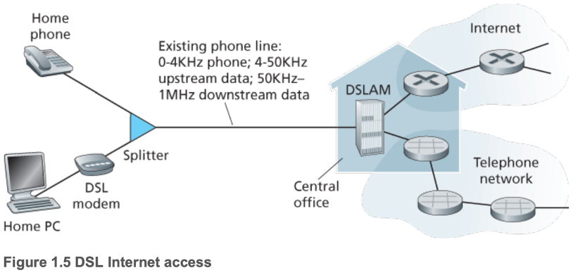
- Often from same local telephone company (telco) that provides local phone access
- Exchange data with a digital subscriber line access multiplexer (DSLAM) located in the telco's local central office (CO)
- DSL modem translates digital data to high-frequency tones
- DSLAM translates back analogue signals from other home PCs to digital data, separates data and phone signals, and sends each into the respective networks
- Residential telephone line carries data and traditional telephone signals simultaneously, encoded at different frequencies
- Upstream and downstream data rates are different (asymmetric)
- Cable
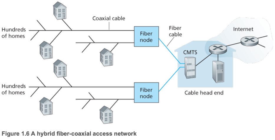
- Uses cable television company's existing infrastructure
- Uses fiber and coaxial cables, referred to as hybrid fiber coax (HFC)
- Cable modems connect to home PCs (similar to DSL modems), convert digital signals to analogue, and divide the HFC network into typically asymmetric channels, defined by Data Over Cable Service Interface Specification (DOCSIS) to be 42.8 Mbps upstream and 30.7 Mbps downstream
- Cable modem termination system (CMTS) converts analogue signal from cable modems back into digital
- Shared broadcast medium majorly hinders downstream rate, and creates the need for a distributed multiple access protocol to coordinate transmissions and avoid collisions
- Fiber to the home (FTTH)
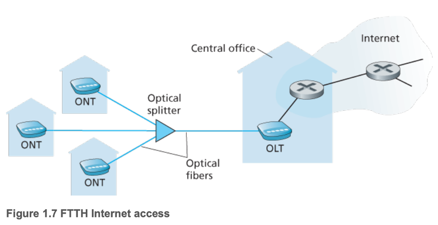
- Active optical networks (AONs) direct signals only to the relevant customer, passive optical networks (PONs) do not
- Also referred to as fiber optic service (FIOS)
- Optical network terminators (ONTs) are present in each home and connect to a neighborhood splitter via a dedicated optical fiber
- Optical line terminator (OLT) convert between optical and electrical signals
- Gigabit per second potential
- Dial-Up
- Over traditional phone lines, based on same model as DSL, slow (56 kbps)
- Satellite
- > 1 Mbps
- Local Area Networks (LAN)
- Access in the enterprise and home typically work using Ethernet switches and WiFi base stations
- Both Mbps to Gbps
- Wide-area wireless access
- Third-generation (3G) wireless, provides packet-switched Internet access at > 1 Mbps
- Fourth-generation (4G)
- Long-Term Evolution (LTE) is similar to 3G, downstream > 10 Mbps
- 1.2.2 Physical Media
- Guided (waves along a solid medium) and unguided (waves propagate in the atmosphere and in outer space)
- Twisted-pair copper wire
- Least expensive, most common guided transmission medium
- Two insulated copper wires ~1 mm thick in a spiral pattern
- Reduces electrical interference from similar close by pairs
- Bundled in a cable
- Single communication link
- Unshielded twisted pair (UTP) is common for LANs, 10 Mbps to 10 Gbps
- Coaxial cable
- Guided and can be a shared medium
- Two concentric copper conductors
- Insulation and shielding
- Common in cable television systems
- High data transmission rates
- Fiber Optics
- Thin, flexible, guided medium which conducts pulses of light
- 10 Gbps to 100 Gbps
- Immune to electromagnetic interference
- Low signal attenuation up to 100 km
- Very hard to tap
- High cost
- Terrestrial Radio Channels
- Carry signals in the electromagnetic spectrum, potentially for long distances
- No physical wire, can penetrate walls, provide connectivity to a mobile user
- Potential packet loss and decrease in signal strength over distance and around/through obstructing objects (shadow fading)
- Satellite Radio Channels
- Geostationary satellites
- Covers same area over Earth over time
- 36,000 km above Earth's surface
- Signal propagation of 280 ms
- >100 Mbps
- Low-earth orbiting (LEO) satellites
- Independent orbit
- Require many satellites to continuously cover an area
1.3 — The Network Core
- 1.3.1 Packet Switching
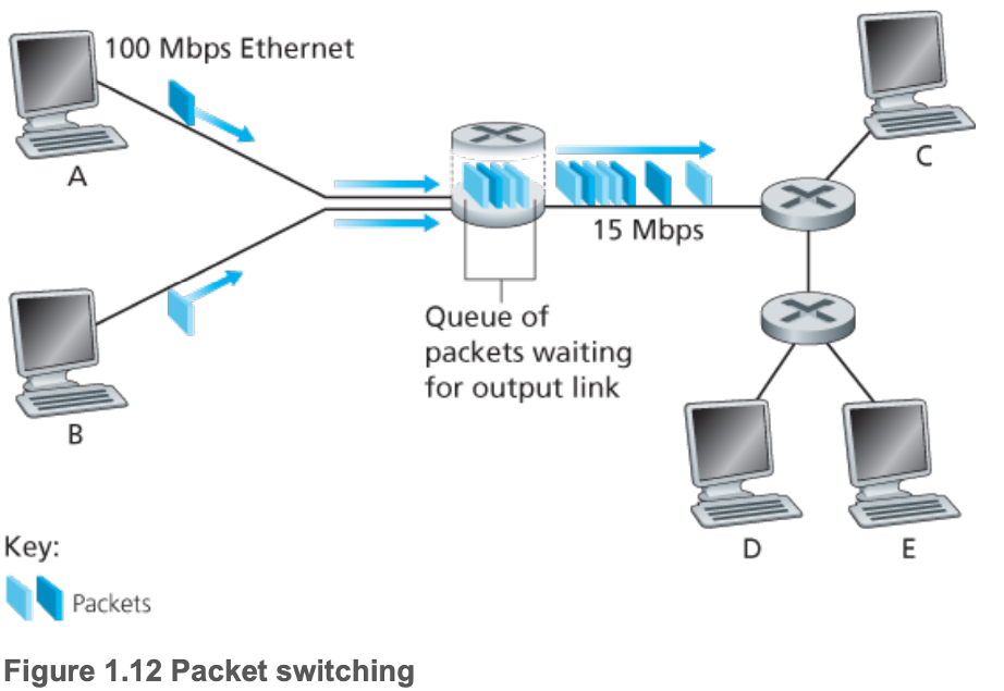
- Long messages are divided into packets
- Packets travel through communication links and packet switches (routers and link-layer switches)
- Store-and-forward transmission: packet switch must receive entire packet before beginning to transmit the first bit of the packet onto the outbound link
- Packet switches have output buffers for each attached link, which store packets before transmission
- Resulting in queueing delays
- Packet loss if the output buffer a packet needs to be placed into is full
- Forwarding tables in each packet switch map portions of destination addresses to outbound links, and the entries of forwarding tables are set by routing protocols
- Advantages
- Sharing of transmission capacity
- Allows for faster service (consider file transfer with TDM and little user activity)
- Simpler to implement
- Less costly
- Provides essentially the same performance as circuit switching and can support significantly more users (because user activity is probabilistic)
- Disadvantages
- Not great for real-time services due to variable end-to-end delays
- 1.3.2 Circuit Switching
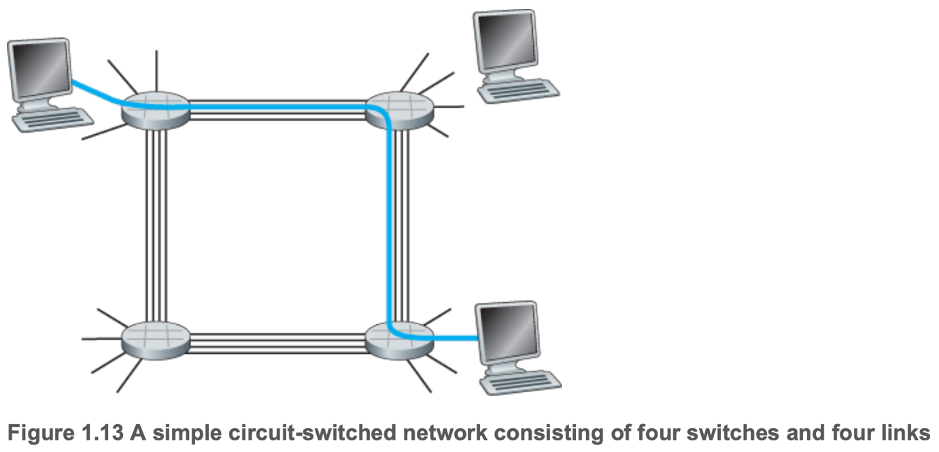
- Resources (buffers, link transmission rate) needed along a path are reserved for the duration of the communication session between end systems
- Traditional telephone networks have this structure
- Circuit: the connection between the sender and receiver
- Multiplexing
- Frequency-division multiplexing (FDM)
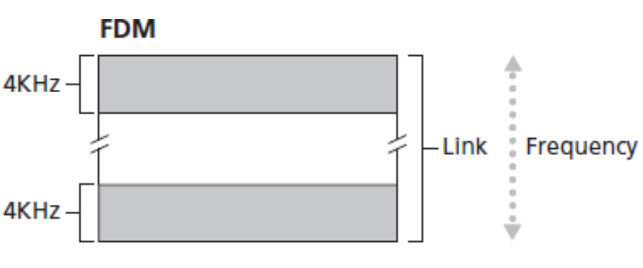
- Frequency band of a link is divided among the connections established across the link
- Bandwidth: width of the frequency band (4 KHz above for both bands)
- FM (frequency modulation) radio stations use FDM
- Time-division multiplexing (TDM)
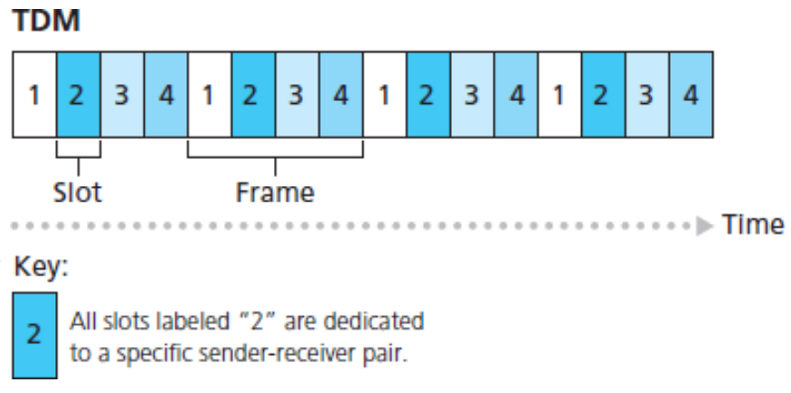
- Time is divided into frames of fixed duration, frames are divided into a fixed number of slots
- Advantages
- Guarantees smooth service
- Disadvantages
- Dedicated circuits waste resources during silent periods
- Difficult to establish end-to-end circuits and reserve end-to-end transmission
- 1.3.3 A Network of Networks
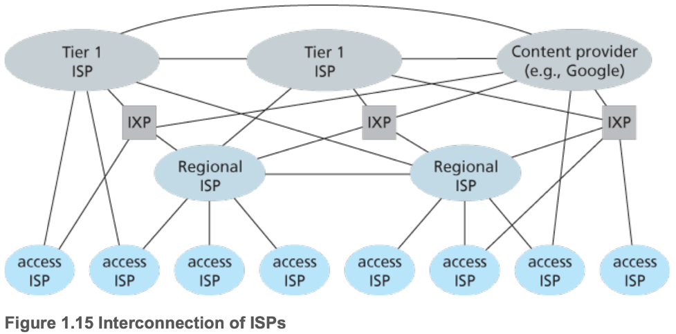
- ISPs are interconnected in a tiered structure
- Access ISPs (customers) pay the regional ISP (provider) it connects to
- Regional ISPs (customers) pay the tier-1 ISP (provider) it connects to
- Regional ISP may be split into provincial ISPs and national ISPs
- Points of presence (PoPs)
- Exist on all tiers above access level
- Are groups of one or more routers at the same location in the providers network where customer ISPs can connect into the provider ISP
- Multi-home: customer ISP connected to multiple provider ISPs
- Peering: pairs of ISPs at the same level can directly connect their networks together
- All traffic between them should only be for direct connections between hosts connected to the ISPs
- Allows them to avoid the cost of routing through provider ISPs
- Internet Exchange Points (IXPs)
- Third parties which create a meeting point for multiple ISPs to peer
- Content-provider networks
- Private networks which try to bypass the upper tiers of the Internet by peering with lower-tier ISPs (either directly or at IXPs)
- Ultimately still have to be customers to tier-1 ISPs, but reduce their costs by exchanging less traffic with them through peering
- Around a dozen tier-1 ISPs
- Hundreds of thousands of lower-tier ISPs
1.4 — Delay, Loss, and Throughput in Packet-Switched Networks
- 1.4.1 Overview of Delay in Packet-Switched Networks
- Total nodal delay
- Nodal processing delay (microseconds)
- Examine packet header
- Check for bit errors
- Determine output link
- Queueing delay (microseconds to milliseconds)
- Transmission delay: transmit packets onto link (microseconds to milliseconds)
- Propagation delay (milliseconds)
- 1.4.2 Queueing Delay and Packet Loss
- Varies from packet to packet, as a result of
- Fluctuations in traffic intensity (\(La/R\))
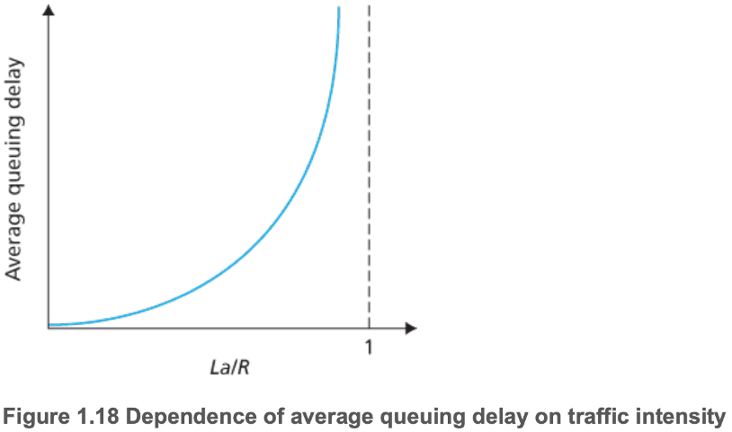
- \(L\) = bit length of packets
- \(a\) = average rate packets arrive at a queue
- \(R\) = transmission rate
- Burstiness of packet arrival
- Packet loss
- Full, finite capacity queues will have to drop packets upon new arrivals
- 1.4.3 End-to-End Delay
- Depends on physical medium
- End systems using shared mediums (such as WiFi) may purposefully delay its transmission as part of its protocol for sharing the medium with other end systems
- Traceroute
- 1.4.4 Throughput in Computer Networks
- Instantaneous and average throughput
- Transmission rate along a path is equal to that of the bottleneck link
- Fluid analogy
- Typically the access network
1.5 — Protocol Layers and Their Service Models
- 1.5.1 Layered Architecture
- Each layer provides its service via
- Certain actions
- Using the services of the layer directly below it
- Advantages to layering
- Easier to update system components
- Disadvantages
- Potential duplicate lower-layer functionality
- Isolation of information
- Internet protocol stack
- Application layer
- Distributed over multiple end systems
- Messages
- Transport layer
- Connection-oriented service to its applications
- Segments
- Network layer
- Host to host
- Datagrams
- Link layer
- Node to node
- Frames
- Physical layer
- Move individual bits within frames from node to node
- Open Systems Interconnection (OSI) protocol stack
- Presentation layer and session layer below application layer
- Presentation layer
- Deals with message interpretation
- Data compression, encryption, and description
- Session layer
- Delimiting and synchronizing data exchange
- Facilitate checkpointing and a recovery scheme
- 1.5.2 Encapsulation
- Packets from above layers become the payloads of packets from below layers, with a new packet header prepended
- Fragmentation
- Tunneling
1.6 — Networks Under Attack
- Malware: malicious software
- Botnet: group of similarly compromised devices
- Malware is often self-replicating: seeks entry into other hosts over the Internet from newly infected hosts
- Viruses: Malware requiring user interaction to infect the user's device
- Worm: Malware that can enter a device without explicit user interaction
- Denial-of-service (DoS) attacks render a piece of infrastructure unusable by legitimate users
- Vulnerability attack to stop services or crash systems
- Bandwidth flooding on the target's access link
- Connection flooding to consume all threads/processes
- Distributed DoS (DDoS) are DoS attacks from multiple sources
- Packet sniffing
- Wireshark
- IP spoofing: injecting packets into the Internet with a false source address
1.7 — History of Computer Networking and the Internet
- 1.7.1 The Development of Packet Switching: 1961 to 1972
- Packet switching as an efficient and robust alternative to circuit switching
- ARPAnet: the first packet-switched computer network
- By the end of the 1969 had 4 nodes
- By the end of the 1969 had 15 nodes
- 1.7.2 Proprietary Networks and Internetworking: 1972 to 1980
- Network control protocol (NCP): first host-to-host protocol
- New packet-switching networks developed: ALOHAnet's microwave network and DARPA's packet-satellite and packet-radio networks
- ALOHA protocol, the first multiple-access protocol (for a radio frequency), was developed
- Internetting: mission to network all created networks
- TCP split into modern day TCP and IP
- Ethernet protocol was built on the ALOHA protocol
- By the end of the decade, there were approximately 200 hosts connected to the ARPAnet
- 1.7.3 A Proliferation of Networks: 1980 to 1990
- Universities linked
- 1983 — transition from NCP to TCP/IP
- DNS developed
- French launched the Minitel project, which aimed to bring data networking into everyone's home
- 1986 — NSFNET (National Science Foundation) created to provide access to NSF-sponsored supercomputing centers
- By the end of the decade, served as a primary backbone linking regional networks
- By the end of the decade, there were approximately 100,000 hosts connected to the ARPAnet
- 1.7.4 The Internet Explosion: The 1990s
- ARPAnet ceased to exist
- 1991 — NSFNET removed its restrictions its the commercial use
- 1995 — NSFNET was decommissioned. Internet backbone traffic was carried by commercial ISPs
- Emergence of World Wide Web application, which was invented at CERN
- Instant messaging
- Peer-to-peer file sharing of MP3s
- Internet startups flooded the stock market, and many collapsed
- 1.7.5 The New Millennium
- Aggressive deployment of broadband Internet access to homes
- Ubiquity of high-speed (> 54 Mbps) public WiFi networks and medium-speed (tens of Mbps) Internet access via 4G cellular telephony networks
- Online social networks
- Private networks by online service providers
- Cloud applications
Chapter 2 — Application Layer
2.1 — Principles of Network Applications
- 2.1.1 Network Application Architectures
- Application architecture dictates how the application is structured over various end systems
- Client-server architecture
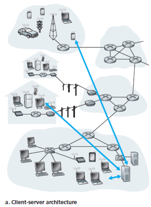
- Server
- Always-on host
- Fixed, well-known IP address
- Client
- Issues requests
- Clients communicate indirectly via a server
- Data centers are used to create a powerful virtual server, to better deal with all of the client requests
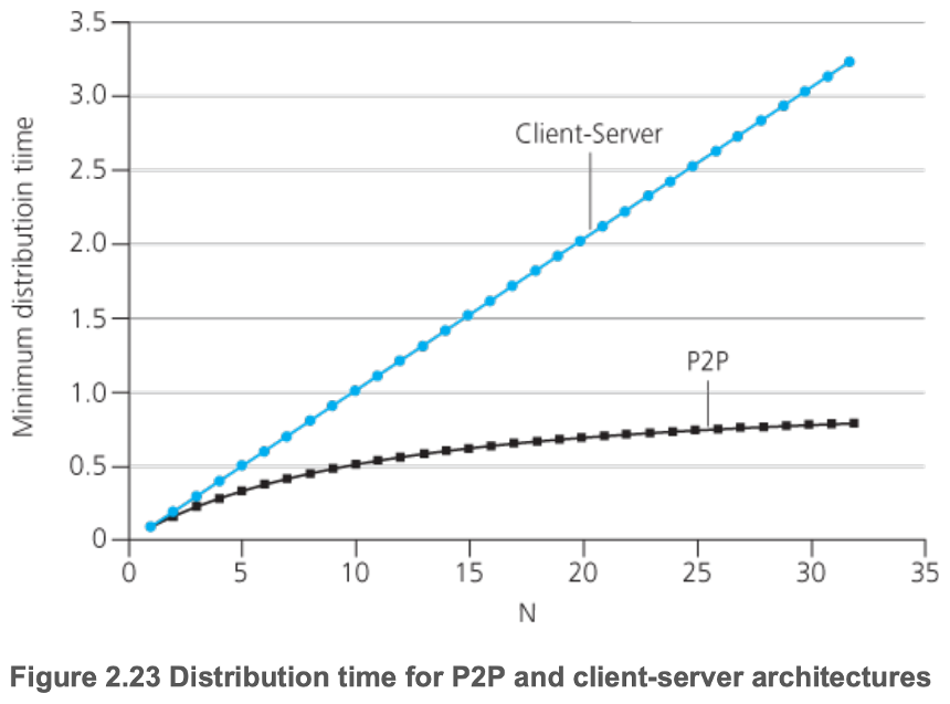
- Peer-to-Peer (P2P)
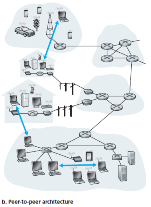
- Minimal (or no) reliance on dedicated servers in data centers
- Direct communication between pairs of intermittently connected hosts (peers)
- Self-scalability
- Peers generate workload by requesting files, but also add service capacity to the system by distributing files to other peers
- Disadvantages due to highly decentralized structure
- Security
- Performance
- Reliability
- Hybrids of client-server and P2P
- For example, many instant messaging applications use servers to track the IP addresses of users, but user-to-user messages are sent directly between hosts
- 2.1.2 Processes Communicating
- Process — program running within an end system by rules governed by the system's operating system
- Want process communication which works independently from the end systems' operating systems
- Processes exchange messages
- Broadly, in each communication session between a pair of processes, there is always a client and server process
- Client process initiates communication, and downloads from a network
- Server process waits to be contacted, and uploads to a network
- Socket: software interface which allows a process to send and receive messages from a network
- Application Programming Interface (API) between the application and the network
- Application developer's control on the transport-layer
- Choice of transport protocol
- Ability to configure transport-layer parameters
- Maximum buffer size
- Maximum segment size
- Host is identified by IP address
- Process is identified by port number
- 2.1.3 Transport Services Available to Applications
- Reliable data transfer
- Sending process can pass its data into the socket and know with complete confidence that the data will (eventually) arrive without errors (likely) at the receiving process
- Not necessary for loss-tolerant applications
- Throughput
- Guarantees are great for bandwidth-sensitive applications
- Not necessary for elastic applications
- Timing
- Guarantees are great for interactive real-time applications
- Not necessary for non-real-time applications
- Security
- Confidentiality
- Data integrity
- End-point authentication
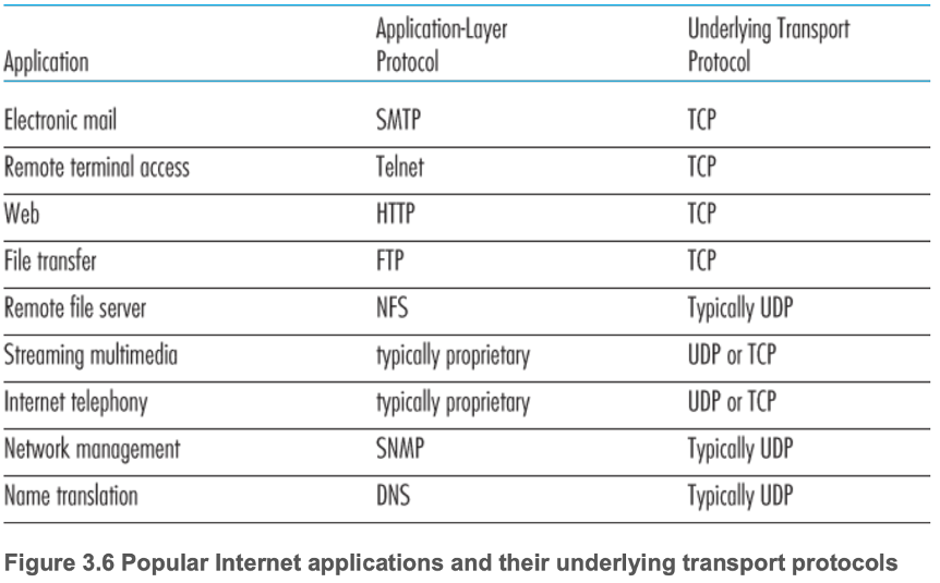
- 2.1.4 Transport Services Provided by the Internet
- TCP
- Connection-oriented service
- Client and server exchange transport-layer control information with each other before the application-level messages begin to flow (handshaking)
- Full-duplex TCP connection forms between the sockets of the two processes
- Reliable data transfer service
- Congestion-control mechanism
- UDP
- Connectionless service
- Unreliable data transfer service
- No congestion-control mechanism
- Security
- Provided by neither TCP or UDP
- Secure Sockets Layer (SSL) enhancement for TCP providing confidentiality, data integrity, end-point authentication
- Implemented in the application layer
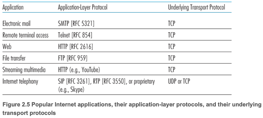
- 2.1.5 Application-Layer Protocols
- Define
- The types of messages exchanged between application processes
- The syntax of various message types (fields and delineation between fields)
- Semantics of the fields
- Rules for determining when and how processes send and respond to messages
- 2.1.6 Network Applications Covered in This Book
- The Web
- Electronic mail
- Directory services
- Video streaming
- P2P applications
2.2 — The Web and HyperText Transfer Protocol (HTTP)
- 2.2.1 Overview of HTTP
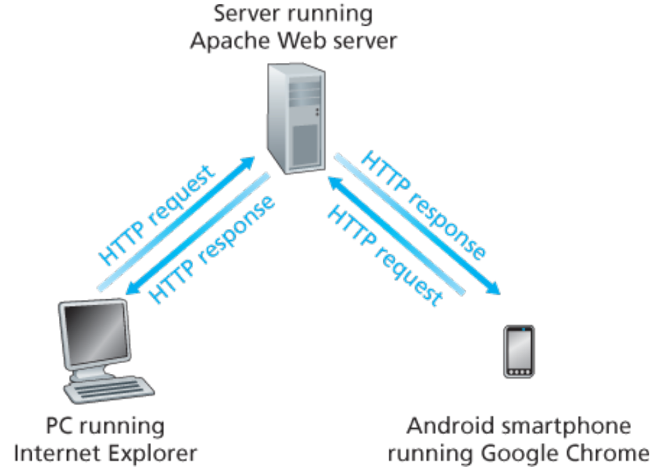
- Web's application-layer protocol
- Implemented in client and server programs
- Web page
- Consists of objects (files)
- Base HTML file with referenced objects
- Each object is addressable by a Universal Resource Locator (URL)
- Uses TCP
- Client-server application architecture
- Stateless
- Maintains no information about the clients
- Persistent connection by default
- 2.2.2 Non-Persistent and Persistent Connections
- Non-Persistent: each request/response pair is sent over a separate TCP connection
- Persistent: each request/response pair is sent over the same TCP connection
- Round-trip time (RTT) — time for a small packet to travel from client to server and then back to the client
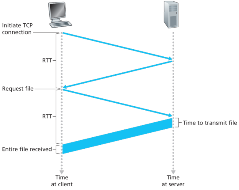
- Persistent connections avoid the extraneous
- Two RTTs per TCP handshake and object request
- Allocation of TCP buffers and variables
- Delay when not using pipelining (HTTP/2)
- 2.2.3 HTTP Message Format
- ASCII
- Request
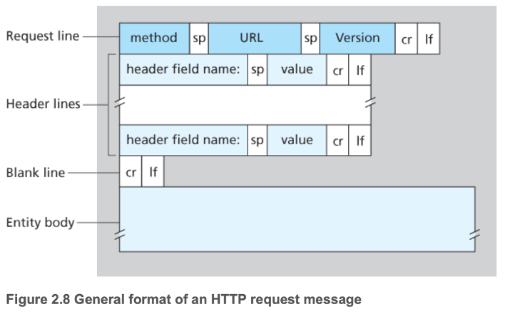
- Methods
- GET
- POST
- HEAD
- PUT
- DELETE
- Browser generates header lines as a function of
- The browser type and version
- User configuration of the browser
- Whether the browser currently has a cached, but possibly out-of-date version of the object
- Response
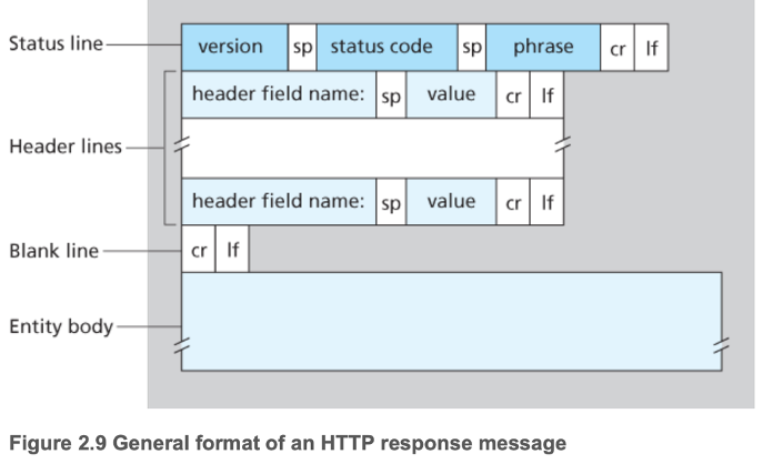
- Web servers generate headers in a similar way to browsers
- Different products, versions, configurations
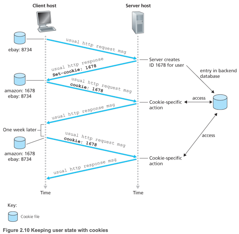
- An HTTP server is stateless
- Simplifies server design
- However, often desirable to identify users
- Cookies
- 2.2.5 Web Caching
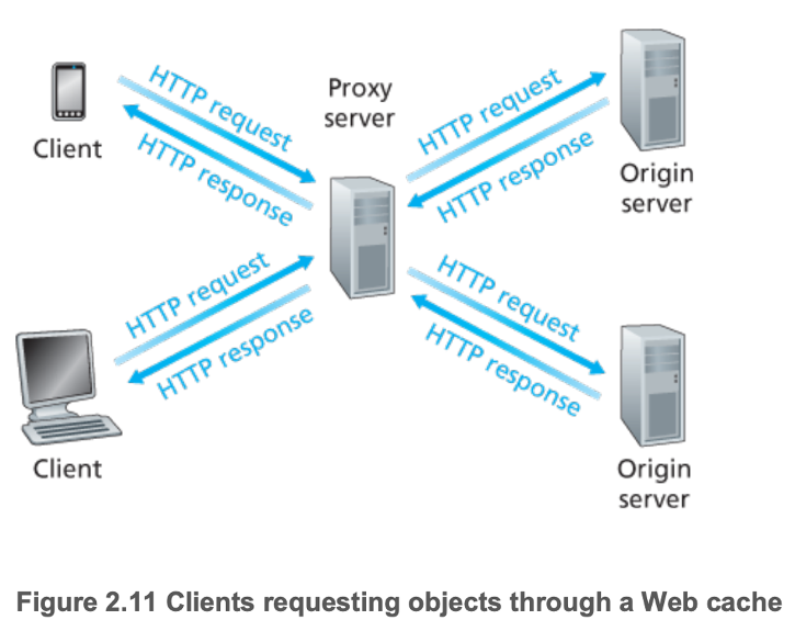
- Functions as both a server and a client
- Typically purchased and installed by an ISP
- Relatively cheap — public-domain software that runs on inexpensive PCs
- Can substantially reduce the
- Response time for a client request
- Traffic on an institution's access link to the Internet
- Web traffic in the Internet as a whole
- Want to maximize cache hit rates
- Content Distribution Networks (CDNs) install many distributed caches throughout the Internet, localizing much of the traffic
- A cache can verify that its objects are up to date using conditional GET messages
- GET method
- If-Modified-Since header
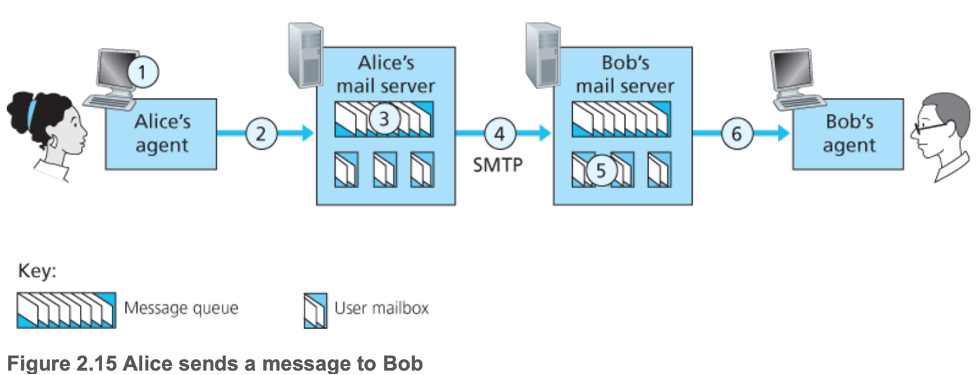
2.3 — Electronic Mail in the Internet
- User agent — allow users to
- Read
- Reply to
- Forward
- Save
- Compose messages
- Mail server
- Each recipient has a mailbox in a mail server, which
- Manages and maintains the messages sent to the recipient
- Authenticates recipients
- Deals with failure
- Holds messages in a message queue and attempts (re)transmission until success
- 2.3.1 SMTP
- Transfer messages from senders' mail servers to the recipients' mail servers
- Everything encoded in 7-bit ASCII (old protocol, designed before people emailed large attachments)
- Common commands
- HELO
- MAIL FROM
- RCPT TO
- DATA
- QUIT
- Each command followed by CRLF
- Terminate DATA with CRLF.CRLF
- 2.3.2 Comparison with HTTP
- Pull vs push protocol
- HTTP is mainly a pull protocol (pulling uploaded information to a server)
- SMTP is primarily a push protocol
- Encoding
- SMTP requires each message to be encoded in 7-bit ASCII format, including non 7-bit ASCII (which is encoded and decoded appropriately)
- HTTP data does not impose this restriction
- Handling other media types
- HTTP encapsulates each object in its own HTTP response message
- SMTP places all of the message's objects into one message
- 2.3.3 Mail Message Formats
- Message header
- From:
- To:
- Subject:
- Blank line after message header, then body
- 2.3.4 Mail Access Protocols
- Could have recipient's local PC run a mail server, to create more direct communication, but recipient's PC would have to be always on and connected to the Internet
- Easier to have the recipient's local PC run a user agent program which pulls from the appropriate mailbox in the appropriate mail server (via a mail access protocol)
- Post Office Protocol — Version 3 (POP3)
- Simplistic — does not carry state information across POP3 sessions
- Does not provide any means for a user to maintain a folder hierarchy on a remote server that can be accessed from any computer
- Internet Mail Access Protocol (IMAP)
- Each message associated with a folder
- Maintains user state information across IMAP sessions
- HTTP
2.4 — DNS — The Internet's Directory Service
- 2.4.1 Services Provided by DNS
- Identify a host via hostname and IP address
- Hostnames preferred by people, fixed-length IP addresses preferred by routers
- Domain name system (DNS) translates memorable hostnames to IP addresses
- Distributed database implemented in a hierarchy of DNS servers
- Often UNIX machines running Berkeley Internet Name Domain (BIND) software
- Application-layer protocol that allows hosts to query the distributed database
- Commonly employed by other application-layer protocols (HTTP, SMTP) to translate user-supplied hostnames to IP addresses
- Host aliasing — hosts with complicated hostnames can have alias names
- Mail server hostname aliasing
- Load distribution
- Servers can be replicated over multiple end systems with distinct IP addresses
- DNS can associate a set of IP addresses with one canonical hostname
- The order of the sequence of IP addresses in the set is rotated within each reply
- Load balances since the first IP address in the reply is commonly used
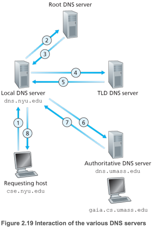
- 2.4.2 Overview of How DNS Works
- Distributed to avoid
- A single point of failure
- High, growing traffic volume
- Having a large distance between querying clients
- Constant maintenance to account for constant new hosts
- Classes of DNS servers
- Root DNS servers
- Provide IP addresses of top-level domain (TLD) servers
- Over 400 scattered globally
- TLD servers
- com, org, net, uk, fr
- Provide IP addresses for authoritative DNS servers
- Authoritative DNS servers
- Houses an organization's publicly accessible DNS records that map the names of hosts within the organization to IP addresses
- Local DNS (LDNS) server
- Provided by ISPs to allow connected hosts to query the DNS database
- In general, TLD servers do not always know the IP addresses of authoritative DNS servers for the queried hostname
- May only know of an intermediate DNS server (often have hostname dns.organization), which knows the authoritative DNS server for the hostname
- Recursive and iterative queries
- DNS servers cache responses to queries for some time (often set to two days)
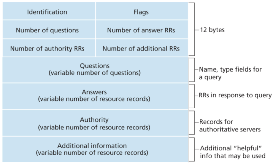
- 2.4.3 DNS Records and Messages
- DNS servers store resource records (RRs)
- Four-tuple (Name, Value, Type, time to live (TTL))
- The meaning of Name and Value depend on Type
- Type=A
- Name is a hostname
- Value is the IP address of the hostname
- (relay1.bar.foo.com, 145.37.93.126, A, TTL)
- Type=NS
- Name is a domain
- Value is the hostname of an authoritative DNS server that knows how to obtain the IP addresses for hosts in the domain
- (foo.com, dns.foo.com, NS, TTL)
- Type=CNAME
- Name is an alias hostname
- Value is a canonical hostname for the alias hostname
- (foo.com, relay1.bar.foo.com, CNAME, TTL)
- Type=MX
- Name is an alias hostname
- Value is a canonical name of a mail server for the alias hostname
- (foo.com, mail.bar.foo.com, MX, TTL)
- MX record allows a company's mail server and Web server to have identical (aliased) hostnames
- nslookup program to send DNS query messages
- Insert records into the DNS database via a registrar
- Commercial entity that verifies the uniqueness of a domain name and enters it into the DNS database for a small fee
- Need to provide names and IP addresses of your primary and secondary authoritative DNS servers
- DNS vulnerabilities
- DDoS to TLD servers
- Partial damage control from caching at LDNS servers
- Man-in-the-middle
- Intercept queries from hosts and return bogus replies
- DNS poisoning attack
- Attacker sends bogus replies to a LDNS server, tricking the server into accepting bogus records into its cache
2.5 — Peer-to-Peer File Distribution
- BitTorrent
- Torrent: collection of all peers participating in the distribution of a particular file
- Peers may selfishly or altruistically leave or stay in the torrent after acquiring the entire file
- Tracker: infrastructure node
- When a peer joins a torrent, it registers itself with the tracker
- The tracker randomly selects a subset of the peers in the torrent and gives their IPs to the new peer
- Peers periodically inform the tracker that they are still in the torrent
- Attempt to form TCP connections with each peer, to form a set of neighboring peers
- Periodically, ask neighboring peers which chunks they have
- Rarest first: request chunks that are the rarest among her neighbors
- Give priority to neighbors that are supplying data at the highest rate (tit-for-tat incentive mechanism)
- Top four highest supply rate neighboring peers are sent chunks back (unchoked)
- Overtime, peers capable of uploading at compatible rates tend to be in each other's neighborhoods
- Every 30 seconds, one additional, randomly selected neighbor is also sent chunks (optimistically unchoked)
- All other neighboring peers not in these five are choked
- Distributed Hash Tables (DHT)
- Database entries distributed over peers in a P2P system
- Partition keyspace
- Ring structure
- Peers know some entries, the IP addresses of their two neighboring peers, and one distant peer
- If peer is queried and doesn't have the corresponding value, asks neighboring/distant peer (whichever is closest to key with respect to keyspace partition)
- Trust neighbors to give true values
- More secure since no single point of failure
2.6 — Video Streaming and Content Delivery Networks
- 2.6.1 Internet Video
- Prerecorded video placed on servers
- Users send requests to servers to view videos on demand
- Video
- Sequence of images being displayed at a constant rate (24-30 images/second)
- Uncompressed image: array of pixels encoded into a number of bits to represent luminance and color
- High bit rate
- Compressible
- To different rates
- For continuous playout, the network must provide an average throughput to the streaming application that is at least as large as the bit rate of the compressed video
- 2.6.2 HTTP Streaming and Dynamic Adaptive Streaming over HTTP (DASH)
- Video encoded into several different versions, each with a different bit rate and, correspondingly, a different quality level
- Allows clients to select different quality chunks based on perceived bandwidth
- Exponentially weighted moving average accounting for variance
- Manifest file: provides a URL for each video version along with its bit rate
- Client selects one chunk at a time by specifying a URL and a byte range in an HTTP GET request message
- 2.6.3 Content Distribution Networks (CDNs)
- Manage servers in multiple geographically distributed locations
- Stores copies of the videos in its servers
- Attempts to direct each user request to a CDN location that will provide the best user experience
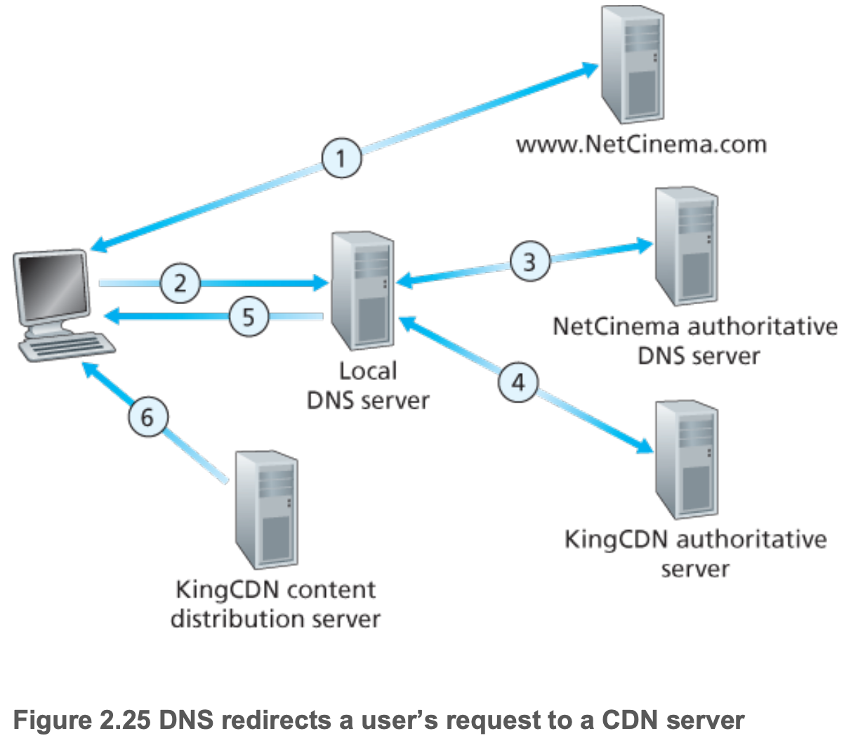
- (Note (6) should be a double-headed arrow)
- Intercept requests for videos using DNS
- Determine a suitable CDN server cluster for that client
- Geographically closest
- Tends to work well for majority of clients
- Can be bad for some, since geographically closest may not minimize number of hops of the network path
- Some end-users are configured to use remotely located LDNSs, in which case this is a bad heuristic for distance
- Ignores variance in delay and available bandwidth over time of Internet paths
- Based on current traffic conditions
- Real-time measurements of delay and loss between clusters and clients
- Make all clusters within a CDN periodically send probes to all LDNSs globally
- Unfortunately, many LDNSs are configured to ignore such probes
- Redirect the client's request to a server in that cluster
- Can be private (Google's CDN) or third-party (Akamai)
- Placement philosophies
- Enter deep: deploy server clusters in access ISPs, globally
- Reduce user-perceived delay
- Highly distributed, difficult to maintain and manage the clusters
- Bring home: build large clusters at a smaller number of sites (typically IXPs)
- Greater user-perceived delay
- Lower maintenance and management overhead
- CDNs may not place copies of every video in every cluster
- Resolved by clusters retrieving the videos from other units and storing a local copy while streaming the video
- Remove videos that are not frequently requested
- Netflix
- Combines Amazon cloud and its own private CDN infrastructure
- Amazon cloud
- Content ingestion: studio master versions of movies are uploaded to hosts in the Amazon cloud
- Content processing: the machines in the cloud create many different formats for each movie (for all client video players), each at multiple bit rates, allowing for DASH
- Uploading versions to its CDN
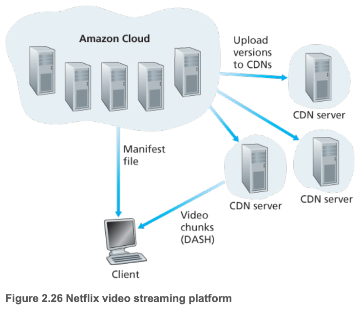
- Initially employed third-party CDN companies to distribute video content, but now has its own private CDN
- Server racks in both IXPs and residential ISPs, combining bring home and enter deep philosophies
- Each server rack has several 10 Gbps Ethernet ports and over 100 terabytes of storage
- Does not use pull-caching — instead uses push caching — caching videos to its CDN servers during off-peak hours
- YouTube
- Private CDN to distribute videos
- Server clusters in many hundreds of different IXP and ISP locations
- Uses pull caching
- Does not use adaptive streaming — instead requires users to manually select a version
- Limits prefetching of video to reduce resource waste via repositioning and early termination
- Processing of uploaded content occurs within Google data centers
- Kankan
- P2P, along with client-server delivery
- Similar to BitTorrent file downloading
- Pushes video content to hundreds of servers in China
- Recently migrated to a hybrid CDN-P2P streaming system
- Client requests beginning of content from CDN servers, and in parallel requests content from peers
- When total P2P traffic is sufficient for video playback, the client ceases streaming from the CDN, only using peers
- If P2P streaming traffic becomes insufficient, the client restarts CDN connections and returns to the mode of hybrid CDN-P2P streaming
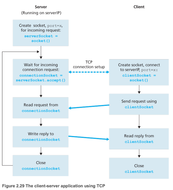
2.7 — Socket Programming
- Send raw byte representation of data
- 2.7.1 Socket Programming with UDP
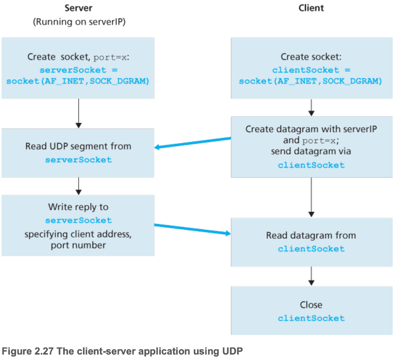
- Specify (server IP, server port) when sending
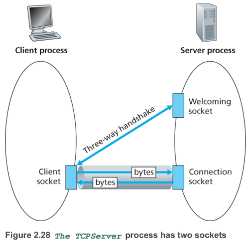
- 2.7.2 Socket Programming with TCP
Chapter 3 — Transport Layer
3.1 — Introduction and Transport-Layer Services
- 3.1.1 Relationship Between Transport and Network Layers
- Transport-layer protocol provides logical communication between processes running on different hosts
- Network-layer protocol provides logical communication between hosts
- Logical communication: appearance of direct connection
- 3.1.2 Overview of the Transport Layer in the Internet
- Internet provides User Datagram Protocol (UDP) and Transmission Control Protocol (TCP)
- Transport layer segments
- Internet's network-layer protocol (IP) is a best-effort (unreliable) delivery service
3.2 — Multiplexing and Demultiplexing
- Demultiplexing: delivering data in a transport-layer segment to the correct socket
- Multiplexing: gathering data chunks at the source host from different sockets, encapsulating each data chunk with header information (for later demultiplexing), creating segments, and passing segments to the network layer
- Uses source and destination port numbers
- 16-bit number ranging from 0 to 65535
- 0 to 1023 are well-known and reserved for use by well-known application protocols
- UDP sockets are fully identified by the two-tuple (destination IP address, destination port number)
- TCP sockets are fully identified by a four-tuple (source IP address, source port number, destination IP address, destination port number)
- Need this additional information due to the protocol being connection-oriented
- Port scanning: determining which applications are listening on which ports
- nmap
- Not always a one-to-one correspondence between connection sockets and processes — today's high-performing Web servers often use one process, and create a new thread with a new connection socket for each new client connection
3.3 — Connectionless Transport: UDP
- Advantages for applications using UDP
- Finer application-level control over what data is sent, and when
- No connection establishment
- No handshaking between sending and receiving transport-layer entities before sending a segment
- No connection state
- Small packet header overhead
- 3.3.1 — UDP Segment Structure
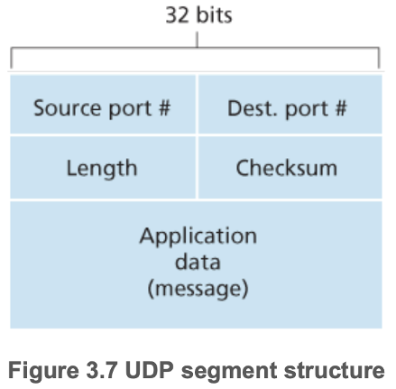
- 3.3.2 — UDP Checksum
- 1s complement of the sum of all the 16-bit words in the segment
- Example of system design's end-end principle
3.4 — Principles of Reliable Data Transfer
- 3.4.1 Building a Reliable Data Transfer Protocol
- Use finite-state machine (FSM) definitions for the sender and receiver
- rdt1.0 — a protocol for a completely reliable channel
- Sending side waits for procedure call from upper-layer protocol and sends packet
- Receiving side waits for procedure call from lower-layer protocol and extracts packet
- rdt2.0 — reliable data transfer over a channel with bit errors
- Need a form of error detection, attach checksum field to all packets
- Need receiver feedback
- Positive acknowledgements (ACK) and negative acknowledgements (NAK)
- NAKs trigger retransmission of packets
- Automatic Repeat reQuest (ARQ) protocols: reliable data transfer protocols based on retransmissions
- Stop-and-wait protocols: sender does not send a new piece of data until it is sure that the receiver has correctly received the current packet (via an ACK)
- rdt2.1 — accounting for potentially corrupted receiver feedback
- Add sequence numbers to packets. That way if the receiver sent an ACK which became corrupted into a NAK, causing the sender to retransmit the packet the receiver already received, the receiver would be able to know that the new packet is a duplicate packet
- rdt2.2 — equivalent to rdt2.1, but is NAK free
- Instead of sending a NAK when receiving a corrupted packet, send an ACK + sequence number for the last correctly received packet
- rdt3.0 — reliable data transfer over a lossy channel with bit errors
- Implement a countdown timer that can interrupt the sender after a given amount of time, which prompts retransmission of the corresponding packet
- rdt3.0 is sometimes known as the alternating-bit protocol, since sequence numbers alternate between 0 and 1
- 3.4.2 Pipelined Reliable Data Transfer Protocols
- Stop-and-wait protocols have very low link utilization
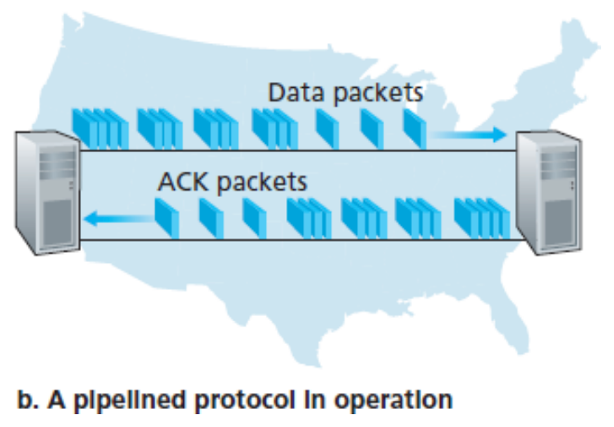
- To accommodate pipelining
- Range of sequence numbers must be increased
- Sender and receiver sides of the protocols may have to buffer more than one packet
- Two approaches: Go-Back-N (GBN) and selective repeat (SR) protocols
- 3.4.3 Go-Back-N
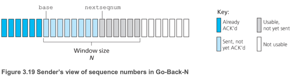
- Sender transmits multiple packets
- Can have no more than \(N\) unacknowledged packets in the pipeline
- Must track this number, and decline the procedure call to send if there are already \(N\) unacknowledged packets in the pipeline
- Limit creates flow control
- Sliding-window protocol: window slides over once base packet is ACKed
- Receiver feedback is a cumulative acknowledgement, indicating that all packets within a sequence number up to and including \(n\) have been correctly received
- Sender starts timers for each transmitted packet. If any of them timeout, the sender retransmits all previously sent, unacknowledged packets (usually equal to window size \(N,\) hence the name Go-Back-N)
- Due to this retransmission of everything, the receiver discards out-of-order packets — no buffering is done
- Bad when window-size and bandwidth-delay product are both large, as many packets can be unnecessarily retransmitted
- 3.4.4 Selective Repeat
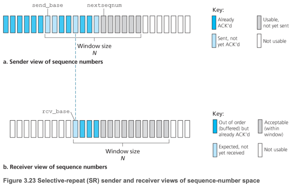
- Same as GBN, except
- Individually acknowledge correctly received packets
- Receiver buffers out-of-order packets
- Potential for receiver to send ACKs for packets with a sequence number below that of rcv_base (if previously transmitted ACK is lost)
- Thus, window size must be at most half of the size of the sequence number space
- Note: have assumed in order delivery
- If not, channel can be thought of as buffering packets and spontaneously emitting these packets at any point in the future
- Due to reusing of sequence numbers, care must be taken to guard against duplicate sequence number, yet distinct packets
- In reality, assume that packets cannot "live" in the network for longer than some amount of time (3 minutes assumed in TCP extensions for high-speed networks)
3.5 — Connection-Oriented Transport: TCP
- 3.5.1 The TCP Connection
- Logical connection, with common state residing only in the TCP processes in the two communicating end systems
- Full-duplex service
- Point-to-point — between a single sender and a single receiver
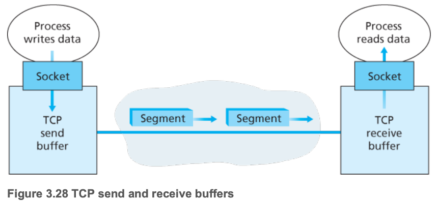
- Application data passed into TCP send buffer
- TCP intermittently passes chunks of data to the network layer
- Maximum segment size (\(MSS\)): maximum amount of data that can be grabbed from the TCP send buffer and placed in a segment (accounting for TCP/IP header length, typically 40 bytes)
- Determined by largest link-layer frame that can be sent by the local sending host (maximum transmission unit (\(MTU\)), usually 1500 bytes)
- Thus typical values are \(MTU = 1500\) bytes, \(MSS = 1460\) bytes
- 3.5.2 TCP Segment Structure
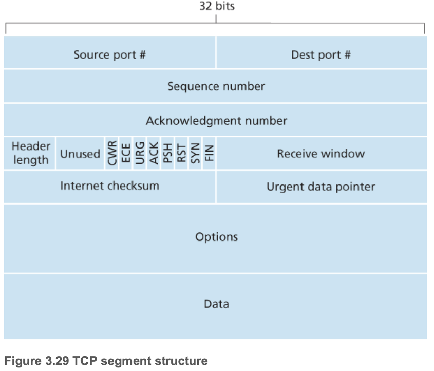
- Flags
- CWR and ECE
- Used for explicit congestion notification
- URG
- Indicates whether data in the segment that the sending-side upper-layer entity has been marked as "urgent" (whose location is pointed to by the urgent data pointer, rare usage in practice)
- ACK
- Indicates whether the value in the acknowledgment number field is valid or not
- PSH
- Indicates whether the receiver should pass data to the upper layer protocol process immediately (rare usage in practice)
- RST, SYN, FIN
- Used for connection setup and teardown
- Sequence number: byte-stream number of the first byte in the segment
- Randomly chose initial sequence number, minimize the possibility that a segment still present in the network from an earlier, already-terminated connection between the same two hosts using the same port numbers is mistaken for a valid segment
- Acknowledgment number: next byte that the sending host expects from the receiving host (cumulative acknowledgments)
- TCP RFC does not impose rules on buffering out-of-order bytes, but in practice this is often done to increase the efficiency of network bandwidth
- Piggybacking: TCP segment with ACK and data
- 3.5.3 Round-Trip Time Estimation and Timeout
- Want timeout to be greater than RTT to avoid unnecessary retransmissions, but not so much larger that link utilization is low
- \(SampleRTT\): amount of time between when a segment is sent (passed to IP process) and received
- Most TCP implementations only take one \(SampleRTT\) measurement (track \(SampleRTT\) for a single transmitted but currently unacknowledged segment) at a time (roughly once per RTT)
- Never tracked for retransmitted packets
- Fluctuates from segment to segment due to congestion in routers and varying load on the end systems
- \(EstimatedRTT = (1 - a) \times EstimatedRTT + a \times SampleRTT\)
- \(a\) is recommended to be 0.125
- Exponentially weighted moving average (EWMA)
- \(DevRTT = (1 - b) \times DevRTT + b \times \lvert SampleRTT - EstimatedRTT \rvert\)
- \(b\) is recommended to be 0.25
- Also EWMA
- Finally, \(TimeoutInterval: EstimatedRTT + 4 \times DevRTT\)
- 3.5.4 Reliable Data Transfer
- TCP ensures that the byte stream that a process reads out of its TCP receive buffer is exactly the same byte stream as that sent by the end system on the other side of the connection
- Specific TCP details and mechanisms
- SendBase variable in TCP sender: sequence number of the oldest unacknowledged byte
- Doubling the timeout interval for a segment after a timeout
- Provides a limited form of congestion control
- Some versions of TCP have an implicit NAK mechanism — TCP fast retransmit
- Three duplicate ACKs for a given segment serve as an implicit NAK for the following segment, triggering retransmission before timeout
- Delayed ACK: when in-order segment arrives with expected sequence number, wait up to 500 msec for the arrival of another in-order segment. If next in-order segment does not arrive in this interval, send an ACK
- 3.5.5 Flow Control
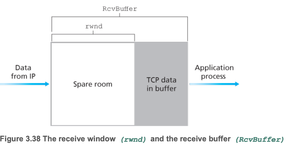
- Eliminate possibility of sender overflowing the receiver's buffer
- Receiver maintains
- \(LastByteRcvd - LastByteRead \leq RcvBuffer\)
- Since overflowing buffers is not permitted
- Receive window \(rwnd = RcvBuffer - (LastByteRcvd - LastByteRead)\)
- Sender maintains
- \(rwnd\) from receiver: how much free buffer space was recently available at the receiver
- \(LastByteSent - LastByteAcked \leq rwnd\)
- Problem: \(rwnd = 0\) being advertised, and sender currently has nothing to send
- Sender will never be told that \(rwnd\) has increased (after application reads from full TCP receive buffer) since this happens only if the receiver needs to send data, or has an acknowledgment to send
- Solution: sender can send segments with one data byte when \(rwnd = 0\)
- Note: UDP does not provide flow control, hence segment loss can occur at the receiver due to buffer overflow
- 3.5.6 TCP Connection Management
- Connection establishment (three way handshake)
- Client-side sends TCP segment (SYN) with
- SYN bit set to 1
- Randomly chosen initial sequence number
- Server-side receives TCP segment and
- Allocates TCP buffers and variables to the connection
- Sends TCP segment (SYNACK) with
- SYN bit set to 1
- Acknowledgement field set to received sequence number + 1
- Randomly chosen initial sequence number
- Client-side receives TCP segment and
- Allocates TCP buffers and variables to the connection
- Sends TCP segment (ACK) with
- SYN bit set to 0
- Acknowledgment field set to received sequence number + 1
- Potential first payload of data
- Connection closing
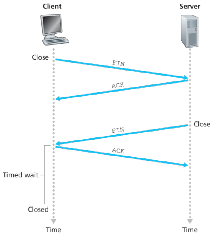
- Close means resources (buffers and variables) are deallocated
- FIN is a TCP segment with FIN bit set to 1
- Timed wait is usually either 30 seconds, 1 minute or 2 minutes
- Afterwards, the connection formally closes and all resources (including port numbers) are released
- SYN flood attack
- DoS
- Send large number of TCP SYN segments, without completing the third handshake step, exhausting the server's connection resources
- Defend with SYN cookies
- In response to TCP SYN, server does not create a half-open TCP connection
- Instead, creates an initial TCP sequence number that is a hash function of source and destination IP, port, and a secret number, and responds with SYNACK segment to the sender of the TCP SYN message
- A legitimate client responds with an ACK segment, whose acknowledgment field = output of hash function + 1
- Server verifies this value using the fields present in the ACK segment, and the secret number stored in memory. If valid, resources are allocated and a fully open connection is created
- Otherwise, no harm is done to the server
- nmap
- Send TCP SYN segment, and either receive
- TCP SYNACK segment
- Application running TCP on corresponding port, nmap returns "open"
- TCP RST segment
- SYN reached target host, but the host is not running an application with TCP on corresponding port
- Not blocked by firewall
- Nothing
- Likely blocked by firewall
3.6 — Principles of Congestion Control
- 3.6.1 The Causes and the Costs of Congestion
- Offered load: sending + retransmission rate of a host onto a link
- Retransmissions, especially unnecessary retransmissions (for example due to a premature timeout) cause link utilization to plummet
- If a packet is dropped along a multihop path, the transmission capacity that was used at each of the upstream links to forward that packet to the point at which it is dropped ends up having been wasted
- 3.6.2 Approaches to Congestion Control
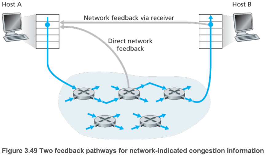
- End-to-end congestion control
- Network congestion must be inferred by the end systems based only on observed network behavior (packet loss and delay)
- Network-assisted congestion control
- Routers provide explicit feedback to the sender and/or receiver regarding the congestion state of the network, typically using a choke packet
3.7 — TCP Congestion Control
- End-to-end congestion control, since the IP provides no explicit feedback to the end systems regarding network congestion
- TCP congestion-control mechanism operating at the sender tracks the variable congestion window (cwnd)
- \(LastByteSent - LastByteAcked \leq min(cwnd, rwnd)\)
- \(min\)(congestion control limit, flow control limit)
- Bandwidth probing: uses ACKs to increase congestion window
- Uses timeouts or three duplicate ACKs to decrease congestion window
- Too small of a value and link utilization is unnecessarily low
- Too high of a value potentially creates lots of congestion, also lowering link utilization (and wasting transmission capacity up to that point)
- Slow start
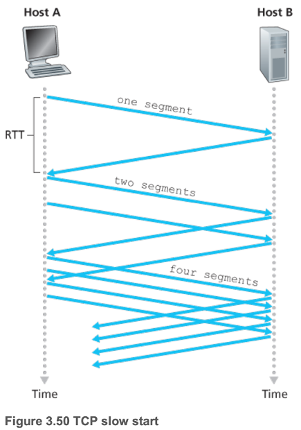
- When a TCP connection begins, the value of \(cwnd\) is typically \(1\;MSS\)
- \(cwnd\) increases by \(1\;MSS\) every time a transmitted segment is first acknowledged
- If there is a loss event
- Slow start threshold (\(ssthresh\)) \(= \dfrac{cwnd}{2}\)
- \(cwnd\) is reset to \(1\;MSS\)
- Slow start is re-entered, until \(cwnd = ssthresh\), in which case congestion avoidance mode is entered
- Congestion avoidance
- Increase \(cwnd\) by \(1\;MSS\) every RTT
- If there is a timeout
- Same as loss in slow start mode
- If triple duplicate ACKs are received
- \(ssthresh = \dfrac{cwnd}{2}\)
- \(cwnd = \dfrac{cwnd}{2} + 3\;MSS\)
- Fast recovery mode can be entered
- TCP Tahoe only uses slow start and congestion avoidance modes
- Fast recovery
- Recommended but not required
- \(cwnd\) increases by \(1\;MSS\) for every duplicate ACK received for the missing segment that caused the entry of fast recovery mode
- When the ACK for the missing segment is received, congestion avoidance mode is entered after setting \(cwnd = ssthresh\)
- If there is a timeout
- Same as loss in slow start mode
- Implemented by TCP Reno
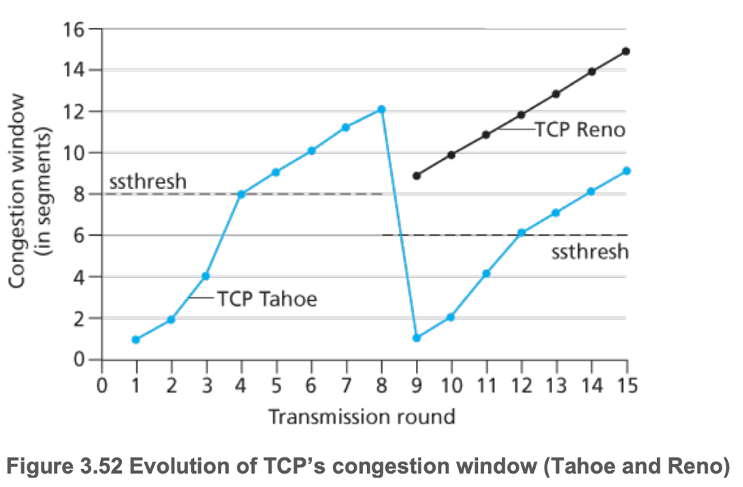
- TCP Tahoe and Reno behave the same until triple duplicate ACK at transmission round 8
- Loss at \(cwnd = 12\), so \(ssthresh = 6\)
- TCP Reno sets \(cwnd = \dfrac{cwnd}{2} + 3 (= 9\;MSS)\) and enters fast recovery mode
- TCP Tahoe sets \(cwnd = 1\;MSS\) and enters slow start mode
- TCP splitting
- Desirable for cloud services to provide a high-level of responsiveness
- If end system is far from a data center, RTT will be large, potentially leading to poor response time performance due to TCP slow start
- Solution: clients establish TCP connection to nearby front-end server. Front-end server maintains a persistent TCP connection to the data center with a large TCP congestion window
- TCP's congestion control is often referred to as an additive-increase, multiplicative-decrease (AIMD) form of congestion control
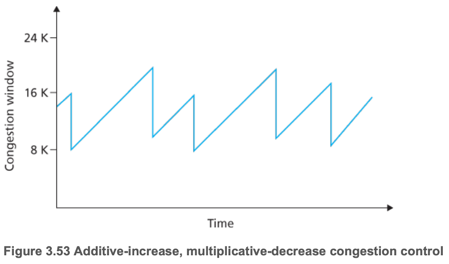
- Ignore slow start
- Assume loss is indicated by duplicate ACKs rather than timeouts
- Assume fast recovery mode is entered
- "Saw tooth" behavior
- TCP Vegas
- Tries to detect congestion in the routers between source and destination before packet loss occurs by observing RTT
- If congestion is detected, lower the rate of transmission linearly
- TCP's congestion control causes it to use high speed links inefficiently
- Only takes one loss event for rate of transmission to completely reset
- Researchers are investigating new versions of TCP for high-speed environments
- 3.7.1 Fairness
- Link capacity split equally among end systems connected to link
- TCP connection 1 and 2 sharing a link of transmission rate \(R\)
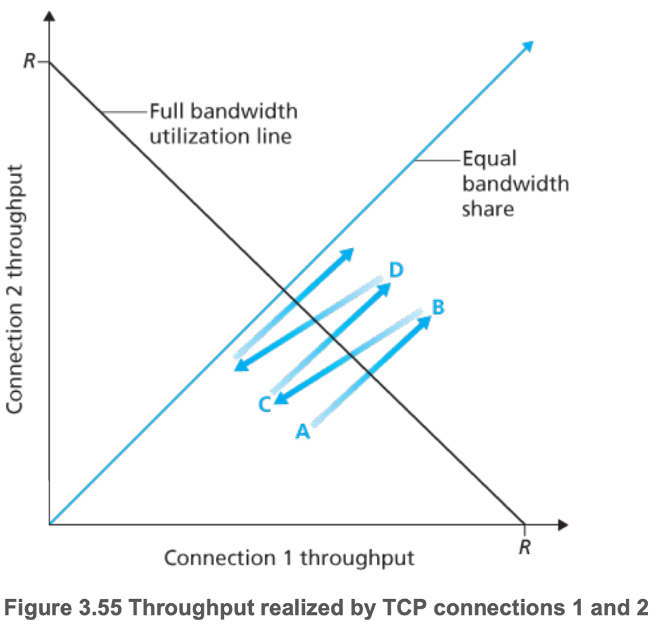
- Start at point A
- Total throughput into link \(< R\), so no loss
- Moves to point B
- Total throughput into link \(> R\), so loss
- Both connections set \(cwnd = \dfrac{cwnd}{2}\)
- Moves to point C
- Connection 1, whose \(cwnd\) was greater than that of connection 2, experiences a greater reduction than connection 2
- Closer to equal bandwidth sharing
- Converges to fairness
- Though in reality, RTT varies
- Hosts with lower RTT are able to grab the available bandwidth (increase their \(cwnd\)) at the link more quickly as it becomes free
- TCP's congestion control mechanism incentivizes high bandwidth applications to run over UDP
- Can use multiple TCP connections in parallel to grab more bandwidth
- 3.7.2 Explicit Congestion Notification (ECN): Network-assisted Congestion Control
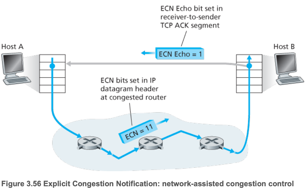
- ECN Echo bit = 1 should cause TCP sender to half \(cwnd\)
Chapter 9 — Multimedia Networking
9.1 — Multimedia Networking Applications
- 9.1.1 Properties of Video
- High bit rate (100 kbps to 3 Mbps)
- Compressible
- Can produce multiple versions of the same video for flexibility
- Redundancy
- Spatial
- Temporal
- 9.1.2 Properties of Audio
- Analogue to digital
- Pulse Code Modulation
- Compressible
- MPEG 1 layer 3 (MP3)
- Advanced Audio Coding (AAC)
- 9.1.3 Types of Multimedia Network Applications
- Streaming stored audio/video
- Streaming: begin media playout after receiving only some of media
- Interactive
- Continuous playout
- Video
- Average throughput is the most important performance measure
- Streamed from CDN or P2P applications
- Conversational voice/video-over-IP
- Voice-over-IP (internet telephony, VoIP)
- Delay-sensitive
- Loss-tolerant
- Streaming live audio/video
- Typically via CDNs
9.2 — Streaming Stored Video
- Extensive client-side application buffering for smooth playback
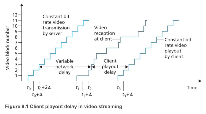
- Absorb variations in server-to-client delay and server-to-client bandwidth
- UDP streaming
- Server transmits video at a rate that matches the client's video consumption
- Typically consists of a small client-side buffer (holds less than a second of video)
- Typically uses the upper-level Real-Time Transport Protocol (RTP)
- Client and server also maintain a separate control connection where the client communicates changes in session state (pause, resume, reposition)
- Disadvantages
- Often fails to provide continuous playout due to fluctuations in bandwidth between server and client
- Requires a media control server, such as a Real-Time Streaming Protocol (RTSP) server to process client-to-server interactivity requests and to track client state for each ongoing client session
- Many firewalls block UDP traffic
- Consequently, rarely used
- HTTP streaming
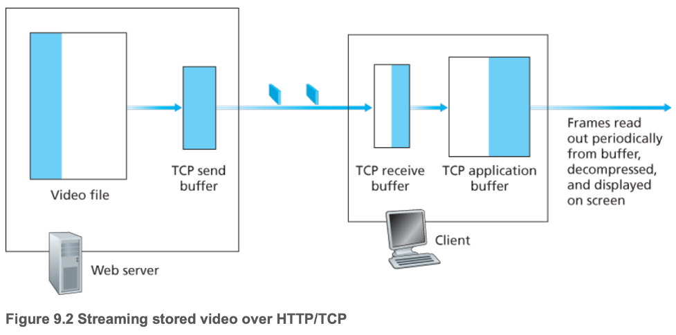
- Server stores video as an ordinary file, addressed by a URL
- Client uses HTTP GET requests over TCP for that URL
- Server sends video as quickly as TCP allows with flow and congestion control
- Client application begins playback once enough bytes are present in the client application buffer (decompresses and displays frames)
- Disadvantages
- Transmission rate often exhibits "saw-tooth" shape as a result of TCP congestion control
- Potential significant delay as a result of TCP's retransmission mechanism
- Fixable with client buffering and prefetching, so typically used today (YouTube, Netflix)
- Prefetching video
- Stored in client application buffer
- "Back pressure" from full TCP buffers will force the server to reduce its transmission rate
- A full client application buffer indirectly imposes a limit on the rate that video can be sent from server to client
- Early termination and repositioning the video
- Client application uses the HTTP byte-range header in the HTTP GET request message to specify the desired frames
- Early termination and repositioning the video waste bandwidth and server resources
- Smaller client application buffers reduce waste
- Adaptive HTTP streaming (Dynamic Adaptive Streaming over HTTP, DASH)
- See 2.6.2
9.3 — Voice-over-IP (internet telephony, VoIP)
- 9.3.1 Limitations of the Best-Effort IP Service
- Receiver must take care in determining
- When to play back a chunk
- What to do with a missing chunk
- Packet loss
- Buffer overflow in routers along path between sender and receiver
- Could be eliminated with TCP, but
- Retransmission mechanisms are often considered unacceptable for conversational real-time audio applications
- Loss would result in reduction of the sender's transmission rate, likely to a rate lower than the receiver's drain rate, possibly leading to buffer starvation and severely impact voice intelligibility at the receiver
- Thus, most VoIP applications run over UDP (Skype, unless a user is behind a NAT/firewall which blocks UDP segments)
- End-to-end delay
- Accumulation of transmission, processing, queuing delays in routers; propagation delays in links; and end-system processing delays
- Perception
- < 150 msecs not perceived by a human listener
- 150 to 400 msecs are acceptable but unideal
- > 400 msecs seriously hinder interactivity
- Packet jitter
- Varying queuing delays at routers
- 9.3.2 Removing Jitter at the Receiver for Audio
- Prepend each chunk with a timestamp
- Delay playout of chunks at the receiver
- Fixed playout delay
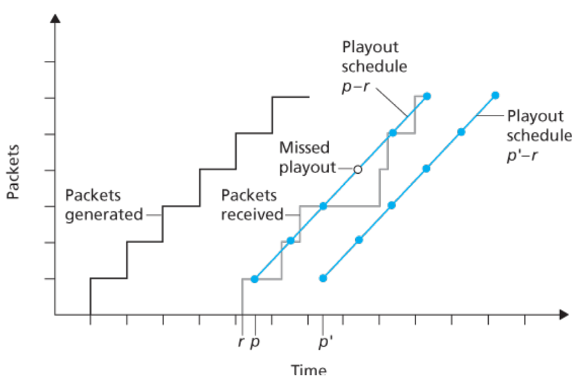
- Receiver attempts to play out each chunk exactly \(q\) msecs after the chunk is generated
- Adaptive playout delay
- Playout time of \(i\)th packet is calculated via estimations of network delay and the variance of the network delay
- Exponentially weighted moving averages for both
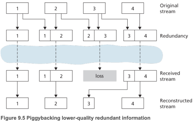
- 9.3.3 Recovering from Packet Loss
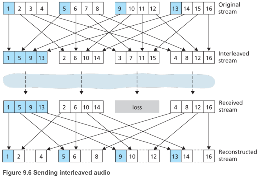
- Loss recovery schemes
- Forward Error Correction (FEC)
- Add redundant information to the original packet stream
- Send a redundant encoded chunk every \(n\) chunks = XOR of the original \(n\) chunks.
- If any single packet in the \(n+1\) packets is lost, the receiver can recover the packet by XORing all of the other packets
- If more than one packet is lost, there is no recovery
- Create lower-resolution audio stream, and prepend already sent packets to new packets
- Interleaving
- Error concealment
- Produce a replacement for a lost packet that is similar to the original
- Possible via short-term self-similarity
- Packet repetition
- Interpolation
- 9.3.4 Case Study: VoIP with Skype
- Proprietary
- Clients can use many different codecs
- Audio and video packets via UDP (by default, TCP otherwise)
- Control packets via TCP
- FEC for loss recovery
- Adapts streams to current network conditions
- P2P
- Skype super peers relay data between two callers behind UDP-blocking NATs
- For video calls with \(N > 2\) participants, each participant's video stream is routed to a server cluster, which relays to each participant the streams of the \(N - 1\) streams of the \(N - 1\) other participants, avoiding the likely low bandwidth upstream links of each participant
9.4 — Protocols for Real-Time Conversational Applications
- 9.4.1 Real-Time Transfer Protocol (RTP)
- Runs on top of UDP
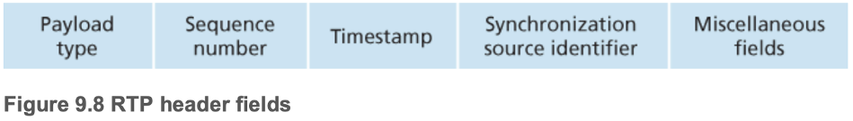
- Payload type = audio or video encoding
- Synchronization source identifier (SSRC) uniquely identifies the source of the RTP stream
- No insurance of timely delivery of data, or other quality-of-service (QoS) guarantees
- 9.4.2 Session Initiation Protocol (SIP)
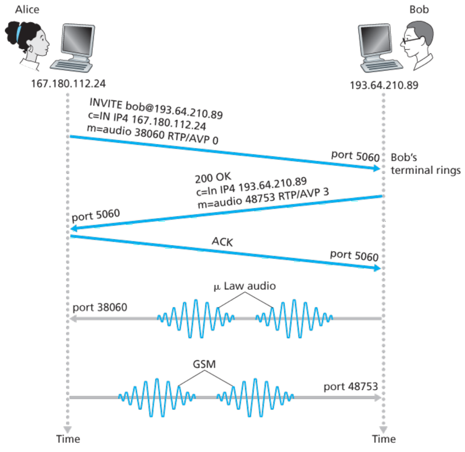
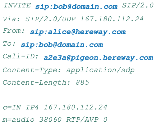
- Establishes calls
- Can allow the caller to determine the current IP address of the callee
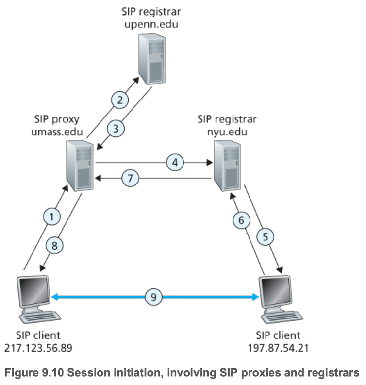
- 1: SIP INVITE message to the umass SIP proxy
- 2: SIP proxy does DNS lookup on the SIP registrar (not shown), and forwards the INVITE message to the SIP registrar
- 3: Redirect response since host is registered with the NYU SIP registrar
- Call management (adding new media streams, changing the encoding of a media stream, inviting new participants to during the call)
- Ends calls
9.5 — Network Support for Multimedia
- 9.5.1 Dimensioning Best-Effort Networks
- Bandwidth provisioning: how much capacity to provide at network links in a given topology to achieve a given level of performance
- Network dimensioning: how to design a network topology (where to place routers, how to interconnect routers with links, what capacity to assign links) to achieve a given level of end-to-end performance
- Need
- Models of traffic demand between network end points
- Well-defined performance requirements
- Models to predict end-to-end performance for a given workload model, and techniques to find a minimal cost bandwidth allocation that will result in all user requirements being met
- Internet could support multimedia traffic at an appropriate performance level if dimensioned correctly, but does not, primarily due to economic and organizational reasons
- Users may not be willing to pay their ISPs enough for sufficient bandwidth to support multimedia applications over a best-effort Internet
- Different ISPs would have to be willing cooperate to ensure that end-to-end paths are properly dimensioned to support multimedia applications
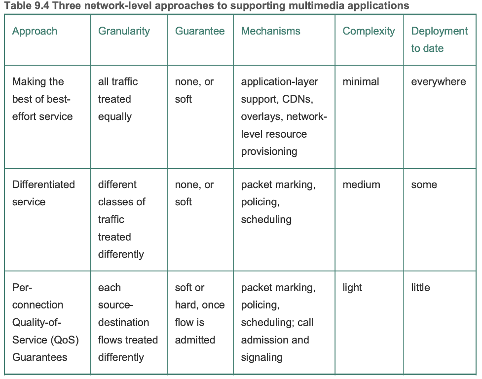
- 9.5.2 Providing Multiple Classes of Service
- Type-of-service (ToS) field in the IPv4 header could be used for packet marking
- Ideally provide traffic isolation among classes, so one class is not adversely affected by another class of traffic that misbehaves
- Traffic policing (drop/delay packets that violate a criteria)
- Link-level packet-scheduling to provide logically distinct links of different capacities within the same physical link
- Desirable to use resources (link bandwidth, buffers) as efficiently as possible
- Better than logically distinct solution since this can waste resources
- Criteria for policing
- Long-term average rate (6000 packets/minute)
- Peak rate (1500 packets/second)
- Burst size (750 packets/instant)
- Leaky buckets
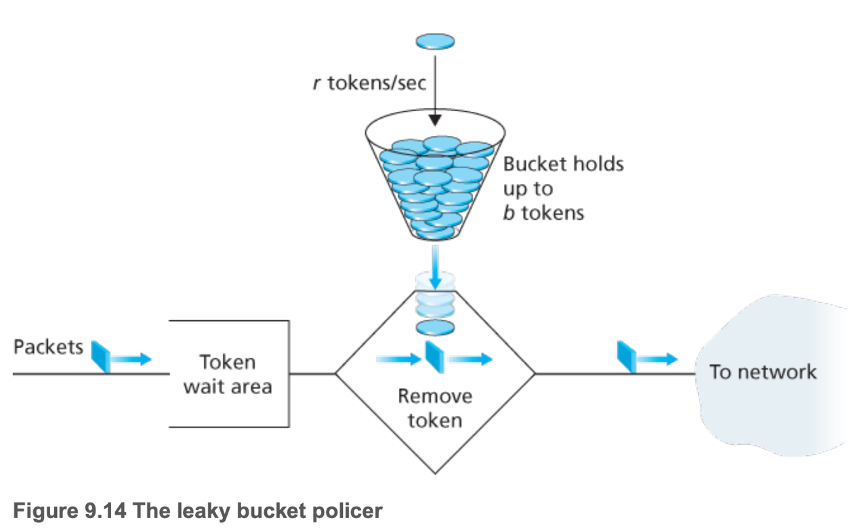
- Packets can only be sent if a token can be removed from the bucket
- Burst rate \(b\)
- Maximum long term average of \(rt + b\), for any length of time \(t\)
- Can use two leaky buckets in series to police a flow's peak rate
- First: flow limited by link (limited to \(r_1 t + b_1\))
- Second: limits flow after initial limit, limiting peak rate (if \(r_2 < r_1\), peak = \(r_2(r_1 t + b_1) + b_2)\)
- Leaky bucket + Weighted Fair Queuing = Provable Maximum Delay in Queue
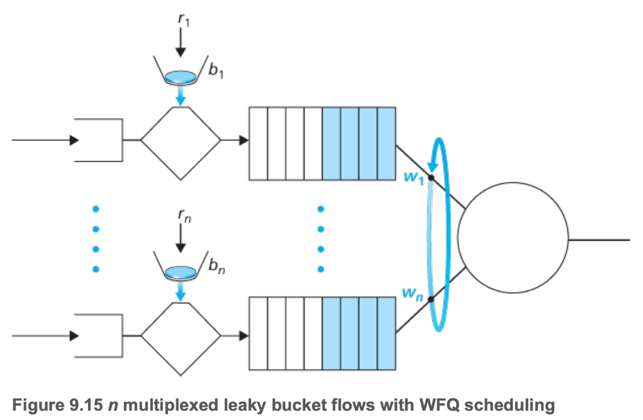
- \(d_{max} = \dfrac{b_1 R w_1}{\sum{w_j}}\) for delay of class 1
- \(R\) is the transmission rate of the link
- If there are \(b_1\) packets in the queue and each packet is removed at a rate of at least \(\dfrac{R w_1}{\sum{w_j}}\), the last packet cannot be removed later than \(\dfrac{b_1 R w_1}{\sum{w_j}}\)
- 9.5.3 Diffserv
- Differentiated service for different classes of traffic
- Network edge router functions: packet classification and traffic conditioning
- Network core router function: forwarding
- Each packet is forwarded onto its next hops according to per-hop behavior (PHB) associated with the packet's class
- Very scalable, no need to maintain connection-specific information
- End users may have to agree to limit its packet-sending rate to conform to a declared traffic profile
- Metering functions compare incoming packet flow with the negotiated traffic profile, determine whether a packet is behaving as expected, and act accordingly (forward if behaving, delay/drop if not)
- Expedited forwarding PHB specifies that the departure rate of a class of traffic must equal or exceed a configured rate
- Assured forwarding PHB divides traffic into four classes, where each class is guaranteed with some minimum amount of bandwidth and buffering
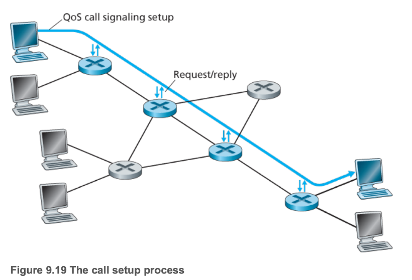
- 9.5.4 Per-Connection Quality-of-Service (QoS) Guarantees: Resource Reservation and Call Admission
- For a network to make guarantees, it must integrate call admission
- A flow must declare its QoS requirement, and have the network either accept the flow (at the required QoS) or block the flow
- This requires the reservation of sufficient resources at each and every network router on its source-to-destination path (call setup)
Sources
Main image: "Internet map 1024" by The Opte Project, hosted by Wikimedia, license
Textbook: Computer Networking: A Top-Down Approach, by James Kurose and Keith Ross